Agilent Instrument User Guide
Agilent
Experimental Workflows
Agilent Operation | Transmission Imaging Workflow
Agilent Operation | ATR Imaging Workflow
Instrument Orientation
FPA Detector and Liquid Nitrogen
The FPA (Imaging) detector is cryogenically cooled for operation with liquid nitrogen. A single detector fill will last for approximately 8 hours. It is very important not to allow the detector to warm up while it is powered on, and especially during data collection. The detector should not be refilled during data collection, so you will need to plan your experiments accordingly.
Liquid nitrogen filling is handled by a Norhof auto-filler, so you do not need to be present at the beamline to refill the detector. The auto-filler operates on a 4 hour refill cycle. It is possible to trigger an early detector fill to accommodate your experimental schedule.
At the end of your beamtime, beamline staff will direct you how to leave the detector / auto-filler. If in doubt, keep the auto-filler running.
Spectrometer and Microscope
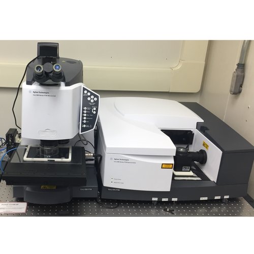
The instrument consists of a spectrometer (Cary 670, on right) and the Cary 620 microscope (right).
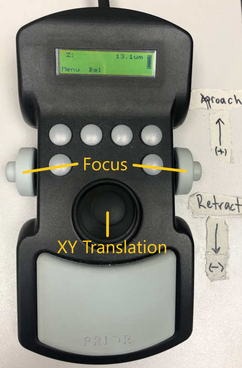
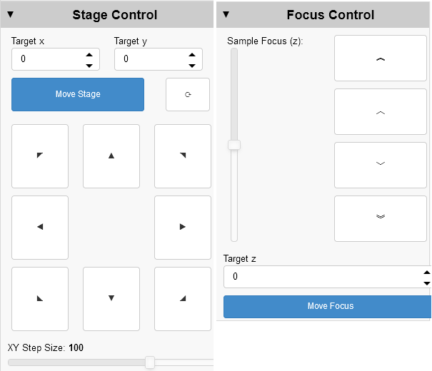
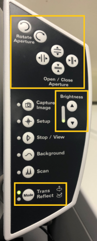
Microscope controls
Manual and software controls exist for most microscope functions.
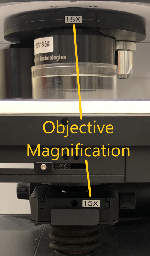
Optics / Accessories
The Cary microscope is equipped with both 15X and 25X magnification objectives, as well as a 4X visible-only objective for sample viewing. There are internal zoom optics available which further increase the magnification by a factor of 5 at the cost of signal intensity at the detector. See the Capabilities section of the Agilent page for more details.
The 15X objective can be configured with a Ge ATR imaging crystal.
The main compartment of the Cary spectrometer can be configured for bulk spectroscopy using standard transmission mounts, a single-bounce Ge ATR or a multi-sample autosampler in both the Mid- and Near-IR.
The purge gas is constantly supplied to the sample but the purge shields must be in place. Ensure the clear plastic top plate and objective collar are in place for at least 15-20 minutes before acquiring data. This will provide adequate time for the purge gas to replace the ambient air in the system after the chamber is closed.
Software
Resolutions Pro (left) is the primary software for instrument control and data acquisition.
The Agilent Wizard (right) software assists with stage control, sample orientation and experiment planning.
Experimental Parameters
Generally,
- Spectral resolution and objective magnification trade off measurement time per area and S/N with increased spectral/spatial resolution.
- Number of scans directly trades measurement time for S/N.
- Pixel aggregation (binning) trades file size and S/N for spatial resolution, with no impact on measurement time.
You may find the Experiment Planning Wizard helpful.
Experimental Setup
These steps should be completed for you by beamline staff, however you should confirm the flap positions and detector cooling before starting your work. If you are remote, you can only confirm that the auto-filler is running.
- Start the Norhof liquid nitrogen auto-filler to cool the FPA using the "Fill FPA" desktop link.
- Open microscope input flap between FTIR and microscope.
- Ensure there is a light path through the main FTIR compartment to the internal DTGS detector and that the compartment flaps are open. Any of the following configurations will work for imaging measurements:
- Pike MIRacle ATR accessory
- Multisample wheel (wheel removed)
- Empty compartment (with purge cover)
- Mode specific setup:
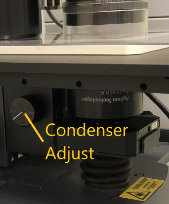
Transmission Confirm that the installed condenser matches the desired magnification
ATR Imaging Confirm the ATR crystal mount is installed and the FPA has been resized to 64x64 pixels - Turn on the detector
Resolutions Pro Method Settings
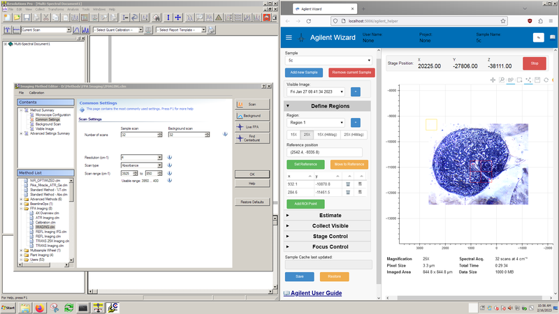
Experimental settings are controlled through the Resolutions Pro Imaging Method Editor.
Settings specific to your experiment can be saved to a custom method in the Users folder. After saving a new method, you should close and re-open the Imaging Method Editor window.
Check the following settings are correct for your measurements:
| Page | Setting | Description | Comment | Remote Control |
|---|---|---|---|---|
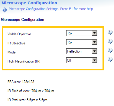
| Microscope Configuration | Visible Objective | Objective used to collect Visible images | Setting must reflect objective in use | ❌ |
| IR Objective | Objective used to collect IR hyperspectral images | Setting must reflect objective in use | ❌ | |
| Mode | Optical configuration, can be Transmission / Reflection / ATR | Changes microscope between Transmission / Reflection optical paths | ✅ | |
| High Magnification | Enable HiMag IR optics (additional 5X) | Adds / removes internal 5X optics from IR optical path | ✅ | |
| Common Settings | Number of scans | Number of co-added scans | Background is commonly set to match sample | ✅ |
| Resolution | Spectral resolution desired | Determines time to collect a single scan | ✅ | |
| Scan type | Y-axis output of calculated spectra (Absorbance/Reflectance) | ✅ | ||
| Scan range | Energy range to store in calculated output | Maximum range (FPA) is 3925 - 850 cm⁻¹, recommended 3900 -- 900 cm⁻¹ | ✅ | |
| Advanced Settings: Collect | Speed | Interferometer mirror velocity | Set to 2.5 kHz for 128x128 FPA | ✅ |
| Interferogram Sampling Interval | Data sampling interval | Set to 4 for 128x128 FPA | ✅ | |
| Number of Pixels Aggregated | Spatial averaging (binning) during collection | Influences S/N and file size, but not collection time | ✅ | |
| Advanced Settings: Spectrometer Configuration | IR Source | Set to "Rear: MIR Source" | ✅ | |
| Beam splitter | Set to "KBr" | Must reflect installed beam splitter | ❌ | |
| Aperture | Set to "Open" for FPA Imaging | ✅ | ||
| Beam Attenuator Throughput | Set to "100%" for FPA Imaging | ✅ |
Agilent Wizard setup
The Agilent Wizard assists with sample location and experiment planning. At a minimum, you should ensure the objective setting on the Define Regions tab matches the infrared objective you plan to use.
Important note: The Agilent Wizard assists with experiment setup and planning, but does not affect the data acquisition step. All data acquisition is controlled through Resolutions Pro.
Mounted Sample Overview Images
You can take 4X visible overview images of your sample(s) to assist with navigation when the purge shield is on. This will be done for you by beamline staff if you are operating remotely.
- Ensure the 4X objective is in place - this step cannot be completed remotely.
- Mount sample(s) on plate, and mount on microscope
- Create a Project folder in the
Z:\drive if not already done, using the User Services Online format (Z:\35G12345~Rosendahl\) - In the Agilent Wizard header, click the ✎ icon and enter User name, Project, and Sample Name of first sample
- Open Imaging Method Editor in Resolutions Pro:
- Select Method "FPA Imaging/4X Overview.clm"
- Visible Image: find focus
- With joystick, mark corners for visible mosaic and Capture
- Tip: If you are noting stage max/min positions while maneuvering around your sample to find corner positions, only use the coordinates provided by the Wizard as these will not be the same as on ResolutionsPro.
- View "Captured visible image"
- Click somewhere on the image to make a single red (IR grid) rectangle
- Using Windows Explorer, copy the 4X
VisMosaicCollectImages_Thumbnail.bmpfromVisMosaicCollectImagesto Project folder
- In the Agilent Wizard:
- Click the "+" button next to "Visible image" list
- Confirm ROI Microscope setting
- Repeat steps 3-5 for each additional mounted sample
- In Wizard: Click "Add new Sample" and update sample name
- In the Agilent Wizard, click the "Save" button.
Overview images can be restored in the case of computer restart using the "Restore" button. - Close Resolutions Pro Imaging Editor window when finished adding overview images
Experimental Workflows
The system is now ready to begin sample measurements.