hATR Microscope User Guide
Instrument Orientation
Detectors and Liquid Nitrogen
Both the single point mapping (MCT) and imaging (FPA) detectors are cryogenically cooled for operation with liquid nitrogen. A single detector fill will last at least 12 hours for the MCT and up to a maximum of 8 hours for the FPA.
-
It is very important not to allow the FPA detector to warm up while is it powered on.
-
The MCT should be allowed to thermalize for 20-30 minutes after filling.
The detector will be initially filled with liquid nitrogen for you by beamline staff, however you will need to plan your experiments to accommodate refilling the detector.
Appropriate PPE is available at the beamline and must be worn whenever handling liquid nitrogen. If you are unsure how to fill the detector or have never done it, ask a member of the beamline staff to demonstrate. You should also have completed the cryogenics safety training module.
Spectrometer and Microscope
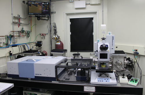
The instrument consists of a spectrometer (Vertex 70v, on left), the transfer optics (plexiglas box in center), and the custom horizontal ATR microscope (hATR). Synchrotron radiation enters the spectrometer from the rear out of the active optics chicane.
Sample Stage Controls
The hATR microscope sample stage can be controlled by a customized ‘hATR Wizard’. The sample position can also be adjusted with the XYZ rotating knobs. The D-rail, which hosts the collection mirrors, can also be controlled with the hATR wizard.
Microscope Coordinate System
Z → vertical direction, raising/lowering the sample away from or towards
the incoming light source.
X → direction parallel to beam path.
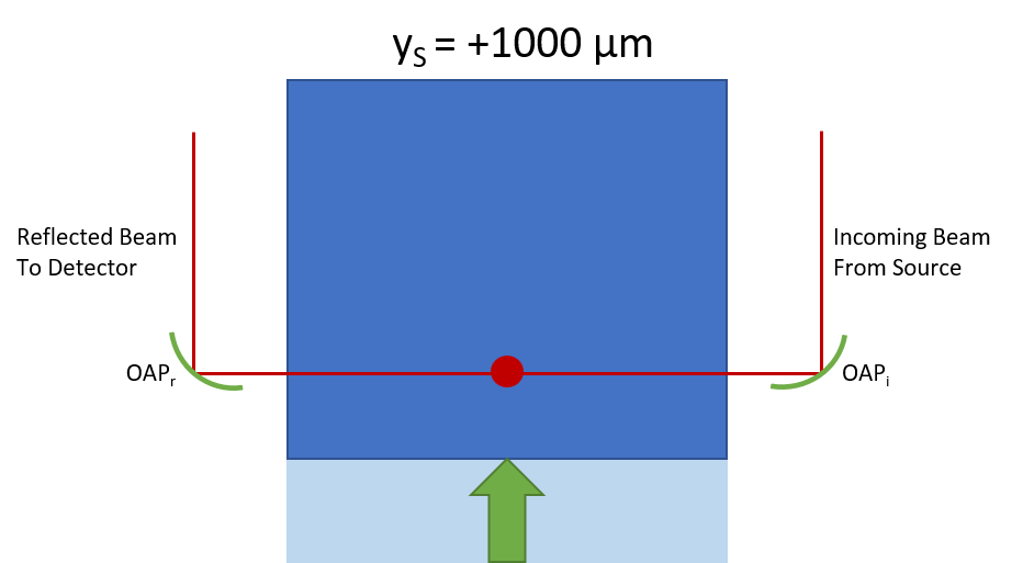
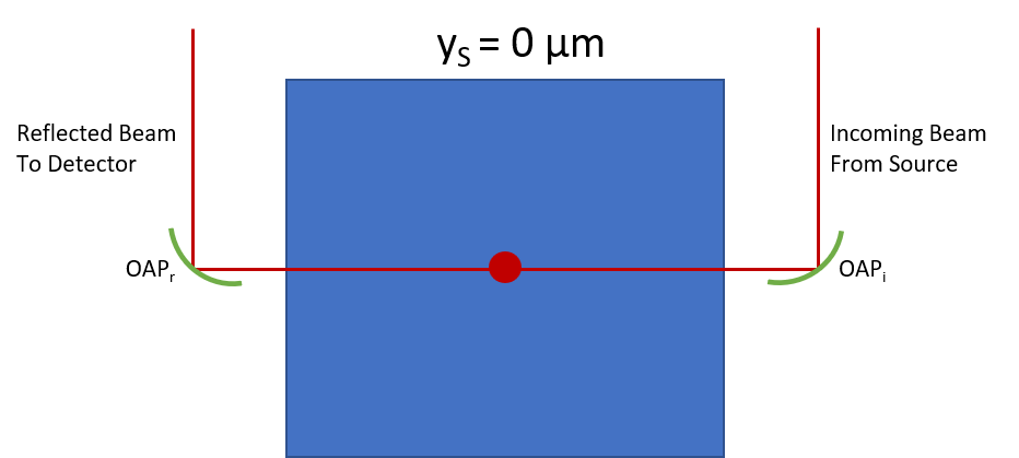
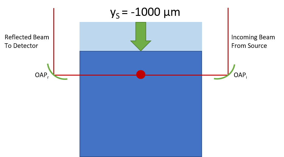
Y → direction perpendicular to beam path. Changes in this direction will not adjust sample ‘focus’
D → collection optics (receival OAP and corresponding flat) are mounted on our d-rail. The rail can be moved toward or away from
the incoming light source.
Navigating Your Sample
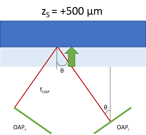
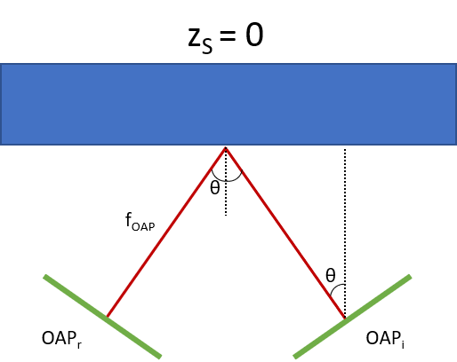
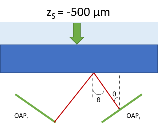
Note on sample stage movement: the beam position is fixed and we translate the sample. Below is a descriptive view of translating a mirror with the stage.
X Direction: Moving Sample Parallel to Beam Path
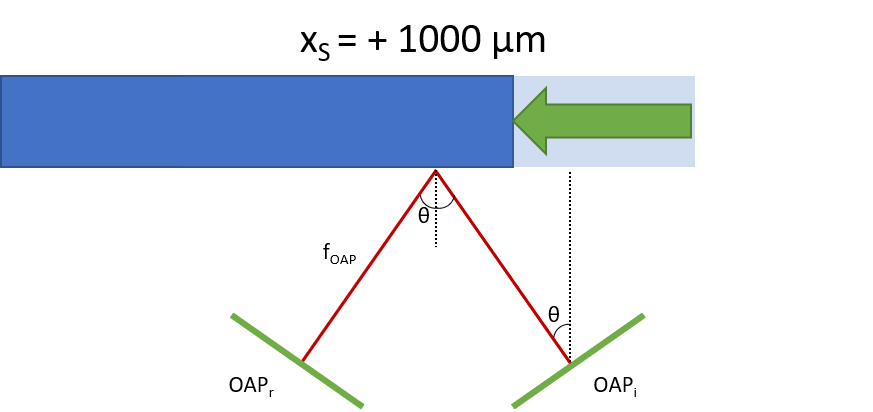
Sample side nearest beam is illuminated.
🟰
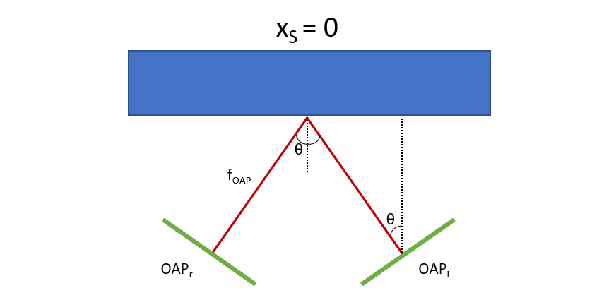
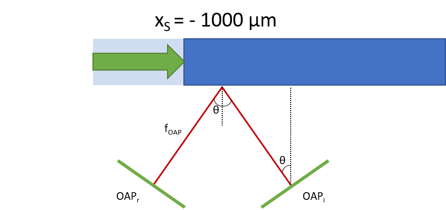
Sample side furthest from beam is illuminated.
Z Direction: Moving Sample Vertically
🟰
🟰
Experimental Setup
These steps should be completed for you by beamline staff, however, you should confirm the detector cooling before starting your work.
-
Fill the detector(s) you will use for your experiments. If you’re using the FPA, turn it ON after it is cooled to liquid nitrogen temp.
-
Confirm the experimental geometry with staff.
-
Start OPUS using the icon in the temp folder on the Bruker desktop.
-
Configure Transfer Optics for experiment.
-
Run the hATR wizard using the Bruker desktop shortcut.
Load Sample onto Sample Stage
Experimental Workflows
The system is now ready to be set-up for your desired experimental workflow.