Return to hATR Microscope Operation User Guide
Internal Reflection for Macro IREs
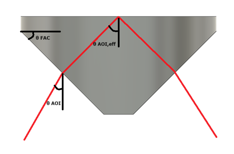
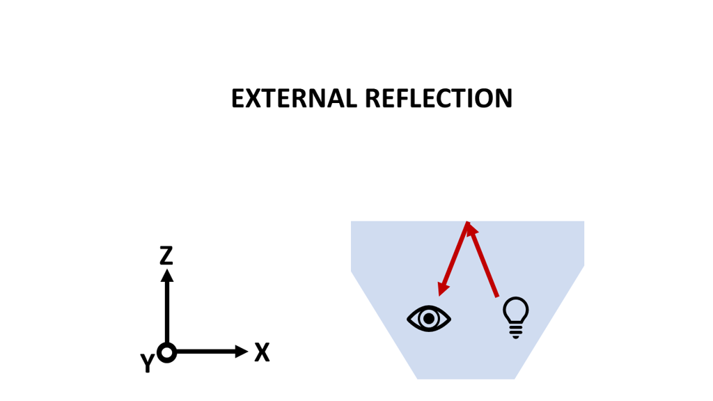
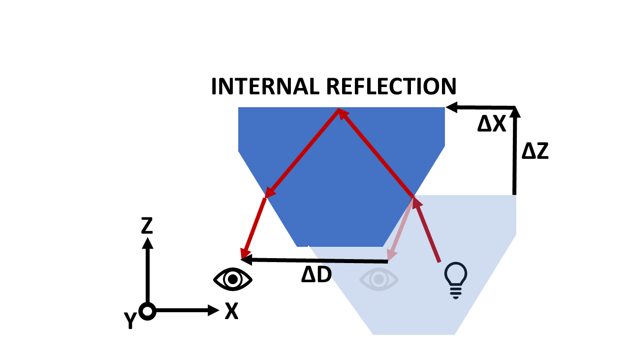
The stage is aligned for Macro IREs, such as FACs, such that external reflection is achieved at the desired IRE/Sample interface height. Depending upon the geometry and material of the IRE, light will take a different path through the crystal than compared to through air (i.e. external reflection). We must translate the crystal such that we achieve total internal reflection at the absolute center of the principal reflection plane of the FAC.
Total internal reflection occurs when a high refractive-index material is in place, like a face-angle crystal or similar, and the light approaches the Sample/FAC interface at an angle equal to or above the critical angle.
We can translate the stage such that total internal reflection will be achieved through your IR once the following information about your sample is known: material, size, face angle, diameter and height. To move from external (through-air) to internal (through-high-refractive index media) one must move the sample away from the source in both X and Z by the calculated amount. This means we increase X and Z by the amounts. Additional translations are required for the receiving optics attached to a rail with position D. One must also increase D by the amount calculated – D will be moved away from the source.
Procedure
Staff will help with this initial set-up.
-
Determine external reflection focus at sample/IRE plane – use mirror on IRE/sample plane. Mirror may be used in the center of the FAC holder. Lower/raise stage z and adjust d to find the focus point, adjust y axis to be at IRE center-point – test with mirror bisecting FAC holder.
Set Current Stage Position XYZ External Reflection
Set Current Rail Position D External Reflection -
Place FAC in holder, ensure proper alignment of FAC in holder – IRE seated into holder properly, IRE face angle perpendicular to beam path, holder fastened to stage adapter plate, stage adapter plate properly seated.
-
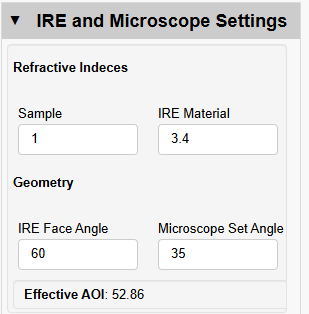
Enter the details for your sample and IRE including:
Microscope set angle (35° unless adjusted)
IRE face angle (45° / 60° / other)
IRE material real refractive index
Sample real refractive index (keep as 1)
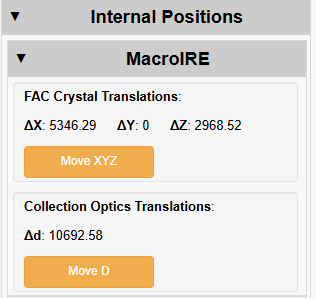
Make sure the above details are correct in the wizard before proceeding with alignment. The wizard will calculate the effective angle of incidence and the crystal translations to align your system in internal reflection. These values are in micrometers.
-
Translate crystal XYZ and collection optics D using the two yellow Move buttons – note that these translations will be unique to each FAC material, FAC geometry and microscope set angle.
-
Verify focus
-
Proceed to measurements
Measurement Area
The center of the FAC (in x and y) is the ideal location for measurement. Some experiments may desire a range of measurement positions such as linescans, point-by-point mapping and imaging of larger regions of samples. The sample stage may be translated in Y for at least 1 cm total range of motion (5 mm on either side of due center). This cut-off is realized due to the geometry of the sample holders. The sample stage may be translated in X away from/toward the source. This results in distortion of the beam through the FAC – the entering beam and exiting beam travel different distances through the high-refractive index medium, causing distortion. Deviations from center will exhibit loss of focus/spatial distortion. It is recommended to stay within 3 mm of center – 1.5 mm in either direction. Therefore, the measurement area is confined to the central 10 mm x 3 mm (Y and X).