Before You Start
- The Germanium single crystal ATR element is very fragile and expensive. You should never touch the crystal. Only clean with alcohols/water and only contact the crystal with appropriate lens paper for cleaning. When your sample is in contact with the crystal do not adjust the microscope stage position - this could scratch the crystal.
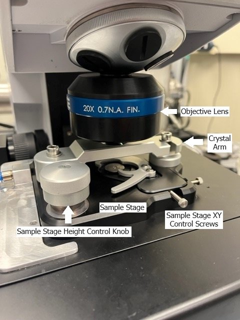
- There are two stages in this procedure, the sample stage and the microscopy stage. Make sure you are comfortable identifying them.
- The sample stage height is controlled by rotating a screw located on the sample stage.
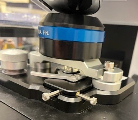
- The microscopy stage height is controlled by either the software or the black focus knob on the white box sitting to the right of the microscope.
- If the stage is moved too far forward it will fall off the rails and need to be reset by the beamline staff. This is avoidable - do not move the stage unnecessarily far away from the sample location. Rotate the objective lens out of the way to give yourself a bit more room to change samples instead of driving the stage away from the lens.
Now - to the science!
1. Select Device
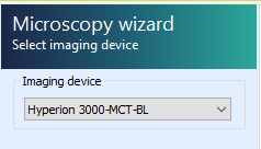
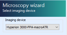
In the OPUS Microscopy Wizard, select the Hyperion 3000-MCT-BL imaging device.
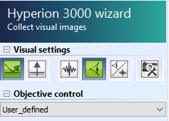
- Select/confirm Hyperion is in visible mode and reflection mode
- Select/confirm "User_defined" objective
2. Define Measurement Location
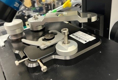
Load your sample onto the sample stage and focus the sample and microscopy stages until the sample is appropriately positioned and in visible focus. Most importantly here - make sure your desired sample location is directly below the objective and centered on the imaging location. Loading a sample is easiest with the objective rotated out of the way and the crystal arm swung out - this will give you more space.
- Confirm that crystal arm is swung out and left screw is tightened
- Place chuck with sample onto macro-ATR sample stage
- Move macro-ATR sample stage xy screws until chuck is reasonably centered
- Raise macro-ATR sample stage z roughly
- Check that the objective is in position - rotate the objective lens into place with the crystal arm swung out.
- Check if top aperture is open
- Lower/raise microscopy stage z until sample is in focus
- ⚠️ (Collision danger) Beware during raising of microscopy stage z that crystal arm does NOT collide with objective
- Use macro-ATR sample stage xy screws until sample are of interest is visible
- Adjust microscope stage z as needed for focus
3. Collect Visible Orientation Image
Take a define overview image of your sample with the visible microscope before infrared measurements will be acquired.
- Press "define overview"
- If no boundary points are set → load boundary points file
- Press "collect defined image"
- Once finished, in stage control select ⭐ and select "Zenith_DATE"
- If not satisfied with sample position repeat from Step 2. Define Measurement Location
🔑 Once satisfied with sample location and visible image, you must lower the sample stage completely before proceeding to avoid collisions! You might also want to remove your sample from the stage to prevent the crystal from coming into contact with the sample before sample measurements are desired. All background measurements can be collected without the sample in place. The sample only needs to be present in Step 8.
4. Focus SIR Light
Find SIR focus with the MCT detector.
- Once sample stage is lowered, loosen screws of crystal arm
- Swing crystal arm into measurement position and tighten screws
- ⚠️ Make sure the washer is positioned ABOVE the arm. See image (right).
- ⚠️ Make sure the crystal does NOT come into contact with the sample.
- Calibrate approximate microscope stage z-position for focus with SIR
- Raise microscope stage z for visible focus.
- ⚠️ (Collision danger) Beware during raising of microscope z that crystal arm does NOT collide with objective
- Raise microscope stage z for visible focus.
🔑 Should be near z=0. Visible light reflection will disappear and re-appear once close to focus. Rough focus is close when aperture is in visible focus when viewed through microscope ocular.
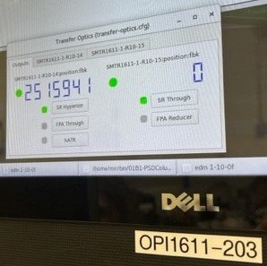
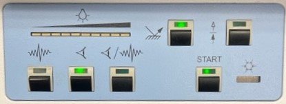
- Change Hyperion to IR mode. → Confirm Transfer Optics are in SR position (touchscreen OPI1611-203)
- Open advanced data collection and check signal tab. → Raise/lower microscopy stage z until counts is maximized (💡>20,000 counts). Rotate the microscopy stage z focus knob only slightly. It is very sensitive. → Change aperture to desired size and optimize z until count is maximized
🔑 Aim for: 0.3 aperture 💡~ 4,000 - 5,000 counts; 0.45 aperture 💡~ 8,000 - 9,000 counts
- Set microscope stage z=0 ("Set to zero"). → ⚠️ From this time point on, do NOT change the microscope z position anymore until finished with all IR measurements at this sample location
5. Take Background for SIR
- In stage control select ⭐ and select "Zenith_DATE" (stage should already be at this position)
- In video wizard, click "next" → "measure background once" → "measure at current position" → "measure background"
- Once complete, click "point at current location" (complete at least once)
- Note, this button looks like crosshairs.
- Check number of scans and wavenumber resolution → click "next"
- Provide sample name. E.g. "sample_SIR_bg" → once complete, click "next" → flat line IR spectra should be visible
6. FPA Background Setup and Calibration
Setup background collection parameters in the video wizard.
- Go back and select
Hyperion 3000-FPA-macroATRimaging device - Change Transfer optics to FPA (touchscreen OPI)
- Open top aperture
- In stage control select ⭐ and select "Zenith_DATE" (stage should already be at this position)
- Click "capture image" → Image should show up left (overview)
- Click "next" → "measure background once" → "measure at current position"
Calibrate FPA field flattening. A bright field image is obtained with all the light entering the detector while a dark field image is obtained with the light blocked from entering the detector.
- In stage control select ⭐ and select "Zenith_DATE" (stage should already be at this position)
- Select "live spectrum" → a flat illumination should be seen
- Right-click right bottom display and select "Customize Focal Plane Array settings..." → Check that FPA settings are set to Offset 255 / Gain 1 / 32.47 µs
- Calibrate FPA Camera
- Deselect the "FPA calibration" checkmark
- Click "acquire bright field image"
- Click "block IR beam" and while detector response is low, click "acquire dark field image"
- Select the "FPA calibration" checkmark and verify
- Click ok → click abort. Note: check whether it goes to next tab
7. Take Background for FPA
Measure the background for the FPA detector.
- Click "measure background". Check that 16 scans will be collected (fewer scans are viable depending on sample)
- Once complete, mark a single measurement tile at the Zenith position → yellow box
- Click "next"
- Provide sample name. E.g. "sample_FPA_bg" → click measure → once complete, click "next" → 2D hyperspectral image with flat line IR spectra at each pixel should be visible
Return to video wizard and return to Zenith position, select ⭐ and "Zenith_DATE"
8. Approach Sample with FPA
We need to make contact with the sample in order to view any spectral information. Raise the sample stage while monitoring the FPA signal until contact is achieved.
- Setup live view of FPA
- In video wizard, click "define overview" → "collect defined image"
- In stage control, select ⭐ and select "Zenith_DATE"
- Once complete, click "next" → "use existing background"
- Click "live spectrum"
- While observing the left display in live FPA, raise the sample stage until contact is made → click "Abort" to leave live FPA view once satisfied.
🔑 Contact is made when 1) a steady change in colour for large areas can be observed in the FPA live view, 2) significant resistance can be felt at the sample raising knob and/or 3) the red limit line at the screw element is visible.
9. Measure FPA Overview
Setup FPA overview collection measurement.
- Right-click the left image tile image and select "load measurement position absolute" → load "
FPA_overview_grid" file - Check measurement is set to desired number of scans (suggested: 16 or fewer scans are viable depending on sample)
- Click "next" → give sample file name, e.g. "sample_FPA_overview_contact-01" → click measure → once completed, click "next"
Inspect the resulting IR image for areas of interest - use Orange workflow to do this. IF no sample is visible or contact with sample in overview is not sufficient, increase pressure between sample and crystal by further raise the sample stage z: repeat procedure from 8. Approach Sample with FPA. IF an area of interest can be found, continue with following SIR measurement by proceeding to Step 10. Otherwise skip to change sample section and attempt measurement with fresh sample.
10. Measure SIR Point-by-Point at Sample Area of Interest
- Setup SIR point-by-point collection
- In video wizard, go back and select "
Hyperion 3000-MCT-BL" - Change Transfer Optics to SR (touchscreen OPI)
- Click "collect single image" - OR defined image to better see the measurement grid
- In stage control select ⭐ and select "Zenith_DATE"
- Once complete, click "next" → "use existing background"
- Change top aperture to either 0.3 or 0.45 based on experiment
- In video wizard, go back and select "
- Setup measurement area
- Place points/line/grid measurement based on location in FPA overview image (from Quasar selection script)
- Check Signal
- Measure SIR
- Click "next" → give file name, e.g. "sample_SIR_region-01_contact-01" → click "measure" → once complete, click "next" and inspect measured IR data
- If a second area of interest is need, repeat steps from Click "collect single image" in Step 10.
- If completed measurement in this sample return to Zenith position (In stage control select ⭐ and select "Zenith_DATE"). Follow sample swap and clean up procedure Bruker Operation | Macro ATR Workflow | Sample Change Procedure